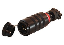

| Duplex Receptacle Table | ||||
| AMPS | INSERT 600 Vac, 60/400 Hz |
INSERT SYMBOL (Click for Diagram) |
RECEPTACLE ASSEMBLY |
KEY POSITIONS |
| 30 | 2 POLE, 3 WIRE | A1 | GD-1716-51SL-L36 | N + 5 |
| 3 POLE, 4 WIRE | A2 | GD-1716-23SL-L36 | N + 5 | |
| 4 POLE, 5 WIRE | B1 | GD-1720-36SL-L36 | N + 2 | |
| 60 | 2 POLE, 3 WIRE | B2 | GD-1720-61SL-L36 | N + 7 |
| 3 POLE, 4 WIRE | B3 | GD-1720-40SL-L36 | N + 4 | |
| NORMAL KEY POSITION = N; ALTERNATE KEYS = 01, 02, ETC. | ||||
| Duplex Ground Power Receptacle Part Number Code Logic | |||||||||||||||
| Duplex | GD | - | A1 | B3 | L | 1 | 2 | - | 93 | B | 6 | 8 | D | 7 | M |
| 1 | - | 2 | 3 | 4 | 5 | 6 | - | 7 | 8 | 9 | 10 | 11 | 12 | 13 | |
|
1 | Classification | GD = Class I, Division 1, Groups C-D, 600 VAC, 60/400 Hertz |
| 2 | Receptacle #1 | ||
| 3 | Receptacle #2 | ||
| 4 | Contact | L = Crimp Type, Silver plated / Standard | |
| 5 | Insert Keying #1 | Omit
for normal (N) key |
|
| 6 | Insert Keying #2 | Omit
for normal (N) key |
|
| 7 | Box Style | 93 = Duplex Receptacle |
|
| 8 | NPT Location | Side
A, B, C, D or E |
|
| 9 | NPT Size #1 | ||
| 10 | NPT Size #2 | Select
from Code Symbol Table |
|
| 11, 12, 13 | Same as 8, 9 & 10 - If Required | ||
| Single Receptacle Table | ||||
| AMPS | INSERT 600 Vac, 60/400 Hz |
INSERT SYMBOL (Click for Diagram) |
RECEPTACLE ASSEMBLY |
KEY POSITIONS |
| 30 | 2 POLE, 3 WIRE | A1 | GD-1716-51SL-L36 | N + 5 |
| 3 POLE, 4 WIRE | A2 | GD-1716-23SL-L36 | N + 5 | |
| 4 POLE, 5 WIRE | B1 | GD-1720-36SL-L36 | N + 2 | |
| 60 | 2 POLE, 3 WIRE | B2 | GD-1720-61SL-L36 | N + 7 |
| 3 POLE, 4 WIRE | B3 | GD-1720-40SL-L36 | N + 4 | |
| 4 POLE, 5 WIRE | C1 | GD-1724-29SL-L36 | N + 3 | |
| 100 | 2 POLE, 3 WIRE | C2 | GD-1724-60SL-L36 | N + 7 |
| 3 POLE, 4 WIRE | C3 | GD-1724-39SL-L36 | N + 5 | |
| 4 POLE, 5 WIRE | D1 | GD-1728-23SL-L36 | N + 3 | |
| 200 | 2 POLE, 3 WIRE | D3 | GD-1728-30SL-L36 | N + 9 |
| 3 POLE, 4 WIRE | D4 | GDU-1728-31SL-L36 | N + 10 | |
| 5
POLE 6 WIRE (3P, 4W, 2 #10 relay contacts) |
D5 | GDT-1728-42SL-L36 | N + 3 | |
| NORMAL KEY POSITION = N; ALTERNATE KEYS = 01, 02, ETC. | ||||
Ground Power Receptacles
Part number code logic information is useful to determine specification of accurate part numbers and to discover product variations and options.
Note: Code logic is provided to identify features called out by standard part numbers. Not all component codes are compatible with all others. Reference part number tables under appropriate product sections or contact us with any questions.
| Single Ground Power Receptacle Part Number Code Logic | ||||||||||||||
| Single | GD | S | - | D5 | L | 1 | - | 92 | A | N | M | E | Q | P |
| 1 | 2 | - | 3 | 4 | 5 | - | 6 | 7 | 8 | 9 | 10 | 11 | 12 | |
1 |
Classification | GD = Class I, Division 1, Groups C-D, 600 VAC, 60/400 Hertz |
| 2 | Controls | Omit if Not
Required |
| 3 | Receptacle | |
| 4 | Contact | L = Crimp Type, Silver-plated / Standard |
| 5 | Insert Keying | Omit
for normal (N) key |
| 6 | Box Style | 92 = Single Receptacle |
| 7 | NPT Location | Side
A, B, C, D or E |
| 8 | NPT Size #1 | |
| 9 | NPT Size #2 | Select
from Code Symbol Table |
| 10, 11, 12 | Same as 7, 8, and 9 - If Required | |
